
The rotary screw belongs to a family of compressors with a positive displacement. Positive displacement pumps generate a flow by providing a expansive cavity toward the suction and a shrinking cavity toward the outlet. The gas trapped inside a positive displacement engine is a constant volume that is subsequently compressed or displaced into the exhaust manifold.
Today, the two most commonly used compressors are a rotating screw (screw rotor) and a reciprocating piston. Compared to these two, the rotary screw does not use valves, it is lighter in weight than the reciprocating piston, is impulse-free, which makes foundation requirements are less extreme and maintaining its structural efficiency at operative times, since the rotors are never in contact with each other come. A screw compressor was originally developed in the mid-1950s and was finally evolved to work between the reciprocating piston and the capabilities of the centrifugal machine for commercial, industrial and gas-type applications.
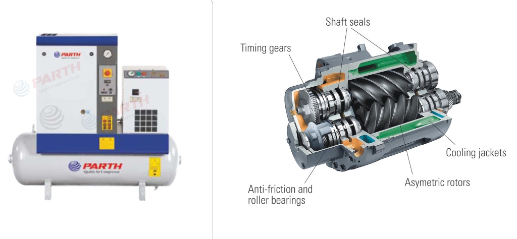
The rotary screw compressor consists of two intermittent helical rotors incorporated into the compressor housing. The Distance between rotors and between housing and rotors is usually .003 to .005 inches. The male or the drive rotor is connected by a shaft extension to an electric motor or engine. In a machine with oil injection, the female rotor is driven by a thin oil layer from the male rotor. A dry rotary screw compressor uses a set of timing gears to achieve proper rotation.
The diameter and length of the rotors control the final pressure and the capacity that the machine can produce. As the diameter of the rotor increases, so does the capacity of the air pumps; As the rotor length increases, the pumps make the final pressure.
When a force is applied to the female rotor, it begins to exit the mesh with the female rotor, creating a void allowing gas to be drawn in through the inlet. As the rotor passes past the inlet, the space between the grids continues to expand until the gas completely fills the space between the blades. When the female rotor enters the aisle space, it begins to transport and compress gas in the direction of the outlet. When the rotors rotate, the gas-filled grooves are insulated by the walls of the housing, creating a compression chamber into which grease is then introduced for cooling, sealing and lubrication.
Continued rotation leads to a decrease in gas volume to the declared design pressure. Compressed gas and lubricant are finally sent through an outlet, then into a two-phase separator, where oil and gas are separated. The oil is filtered using a 10 micron automobile type centrifuge on a filter and then cooled with air or water before being re-injected into the compression chamber. The type of oil used in these machines is a synthetic hydrocarbon with a viscosity of ISO 100, 150 or 220 and is selected based on the specific gravity of the gas. Correct gas analysis is critical when choosing an oil, as during the initial start-up, the gas will reduce the viscosity of the oil. In the case of an air compressor, the gas is then sent to an air-cooled air cooler where up to 70% of the absorbed water vapor is condensed from the gas stream before entering the supply manifold.
The compression port is positioned and cut to achieve an application pressure ratio. To achieve maximum efficiency, the central geometry meets the requirements of the application pressure. Some designs of rotary screw compressors use an adjustable discharge valve that continuously searches for maximum efficiency, opening and closing, depending on the pressure conditions in the system. When the compressor detects a decrease in the air demand of the system (pressure increase), the exhaust valve allows air to circulate back to the inlet without compression to satisfy the needs of the system. The result is a shorter rotor, resulting in variable displacement operation, which reduces power requirements.
The displacement of the screw compressor depends on the volume and speed of the row spacing. The row spacing depends on the profile, length and diameter of the rotor. The row spacing can be expressed by the equation;
Qr = d3 (L/d) / C
Where: Qr = Displacement / Turnover d = rotor diameter C = typical profile constant
Qd = Qr x N
Where: Qd = discharge volume N = compressor speed Qi = Qd x Ev
Where Qi = actual input volume Ev = volumetric efficiency
Volumetric efficiency is the slip function of the rotor, which is the internal leakage created by the expansion of the gas towards the low pressure side, thus reduces the potential volumetric capacity of the compressor.
The discharge temperature of a screw compressor can be estimated assuming adiabatic compression, assuming that energy (heat) is not transferred to or from the gas during compression, and all delivered work is added to the internal energy of the gas, which leads to an increase in temperature and pressure.
The discharge temperature can be calculated by taking an adiabatic increase in temperature and dividing it by adiabatic efficiency, and then multiplying by the efficiency of increasing the temperature to take into account cooling. To determine the final discharge temperature, add the inlet temperature to the increase in temperature.
Parth Compressor is one of the leading screw compressor manufacturers in India, With 25 years manufacturing experience offering innovative rotary screw compressors from 5 HP up to 100 HP and produce energy-efficient screw compressor, compact design, low power consumption and noise-free compressors.


You must be logged in to post a comment.